Automatic Temperature Controlled Fan Using Arduino
Fan Speed Controlled by Temperature and Arduino. To add a simple RC filter at the output of the PWM pin on the Arduino board. Schematic of the Automatic Fan Speed.
Tum Hi Ho Remix top song is Tum Hi Ho Remix. Tum Hi Ho Remix Song From Vidhya Vox Free Mp3 Download Play and Download official english version of tum hi ho you re the one by lenin jacob hope you like it for more english versions follow us today or like our facebook page share if you like our songs Tum Hi Ho English Version by Lenin Jacob Viral on Youtube, Whatsapp and Facebook.  The media files you download with rsymedia.
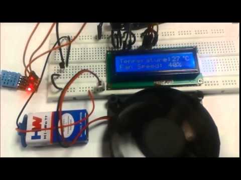
In this arduino based project, we are going to control DC fan speed according to the room temperature and show these parameter changes on a 16×2 LCD display. It is accomplished by the data communications between Arduino, LCD, DHT11 sensor Module and DC fan that is controlled by using PWM. PWM is a technique by using which we can control voltage. Circuit Components • Arduino UNO • DHT11 sensor • DC Fan • 2n2222 transistor • 9 volt battery • 16×2 LCD • 1K resistor • Connecting wires This project consists of three sections. One senses the temp erature by using humidity and temperature sensor namely DHT11.
Second section reads the dht11 sensor module’s output and extracts temperature value into a suitable number in Celsiu s scale and control the fan speed by using PWM. And last part of system shows humidity and temperature on LCD and Fan driver.
Here in this project we have used a sensor module namely DHT11 that are already have discuss our previous project namely “”. 

What is PWM? PWM is a technique by using we can control the voltage or power. To understand it more simply, if you are applying 5 volt for driving a motor then motor will moving with some speed, now if we reduces applied voltage by 2 means we apply 3 volt to motor then motor speed also decreases. This concept is used in the project to control the voltage using PWM. (To understand more about PWM, check this circuit: ) The main game of PWM is digital pulse with some duty cycle and this duty cycle is responsible for controlling the speed or voltage. Suppose we have a pule with duty cycle 50% that means it will give half of voltage that we apply. Formula for duty cycle given below: Duty Cycle= Ton/T Where T= total time or Ton+Toff And Ton= On time of pulse (means 1 ) And Toff= Off time of pulse (means 0) Read More.